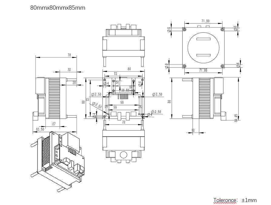
The hhl-8500-cw-1n transmitter adopts 8.5um QCL laser in continuous or pulse mode. Pulse width range: 1ns-200ns, repetition rate up to 300MHz. It can transmit 155mbps-622mbps (OC-3, oc-12) bitstreams. Differential input, minimum input voltage swing 200mV. Dual power supply (+ 5V, + 12V). Laser temperature control range: 15 ° c-28 ° C (customized according to user requirements). The average output power is 250 mW. Integrated thermal protection, over-voltage protection, over-current protection, reverse power supply protection. The threshold current, optical power, extinction ratio and swing amplitude of QCL laser can be adjusted. Small size, low power consumption, high speed, easy to connect and use. It is the world's fastest mid infrared emission module.
Applications:
- mid infrared space communication
- Middle infrared spectrum analysis
- mid infrared gas detection
- mid infrared imaging
- mid infrared radar
- mid infrared medical
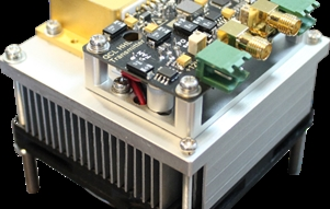
Photoelectric parameter index
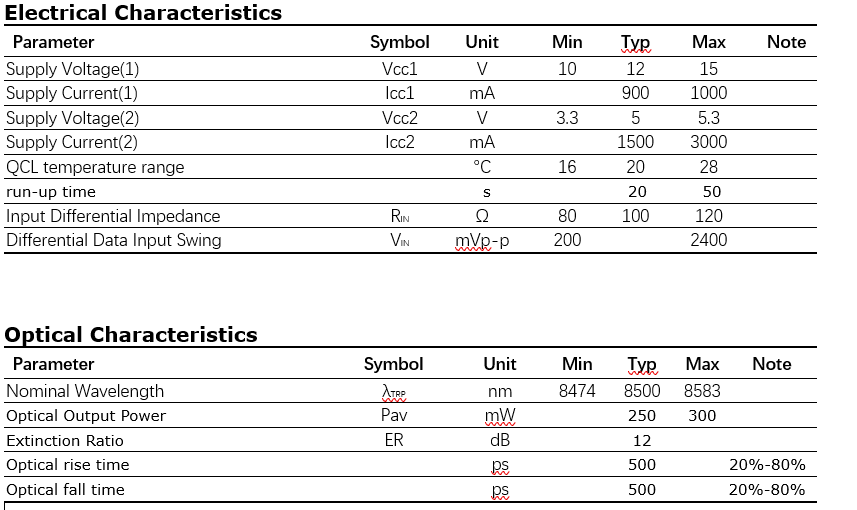
Principle and operation
QCL working temperature regulation
The working temperature of QCL can be obtained by adjusting VR3 and measuring T1 voltage, and the corresponding working temperature will be increased by 1 ° C for every 156mv increase. The common values are as follows:
VT1=1.25V=20°C;VT1=2.5V=28°C;VT1=0.63V=16°C
CW working mode
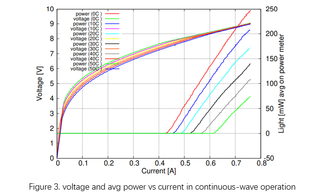
A. Measure the voltage VB at both ends of the constant current source sampling resistor R7, Ibias = VB △ R7, adjust VR2 to the target output average optical power according to the corresponding relationship between Fig. 2 and Fig. 3, and check whether it meets the target value with the optical power meter, and the maximum Ibias = 0.75a.
B. According to the requirements of Figure 1, input the signal, connect the photodetector to the oscilloscope, and observe the quality of the light waveform. Adjust VR1 to change the gain of power amplifier to the best waveform quality; adjust vr4 to change the bias voltage of power amplifier. The higher the bias voltage, the greater the modulation current, the greater the amplitude of waveform and the greater extinction ratio. The maximum modulation current is 1 A. The combination of VR1 and vr4 achieves the best waveform quality and amplitude.
C. When the input signal is bit stream, please pay attention to the encoding mode. It is suggested that the number of continuous codes should be less than 7. 8B / 10B encoding can ensure the minimum jitter performance. Transmission rate range: 155mbps-622mbps。
Pulse mode
A. Measure the voltage VB at both ends of the constant current source sampling resistor R7, Ibias = VB △ R7, adjust VR2 to near the threshold value of QCL according to the corresponding relationship between Fig. 2 and Fig. 3, and check whether the output optical power meets the definition of no light with optical power meter, and the maximum Ibias = 0.75a.
B. According to the requirements of Figure 1, input the signal, connect the photodetector to the oscilloscope, and observe the quality of the light waveform. Adjust VR1 to change the gain of power amplifier to the best waveform quality; use optical power meter to measure the output average optical power under different pulse width and repetition frequency, and adjust vr4 to change the bias voltage of power amplifier. The higher the bias voltage is, the greater the modulation current is, the greater the waveform amplitude is, and the greater the extinction ratio is, the greater the average optical power output is. The maximum modulation current is 1 A. VR1 and vr4 are combined to achieve the best waveform quality, edge velocity, pulse amplitude and average output power.
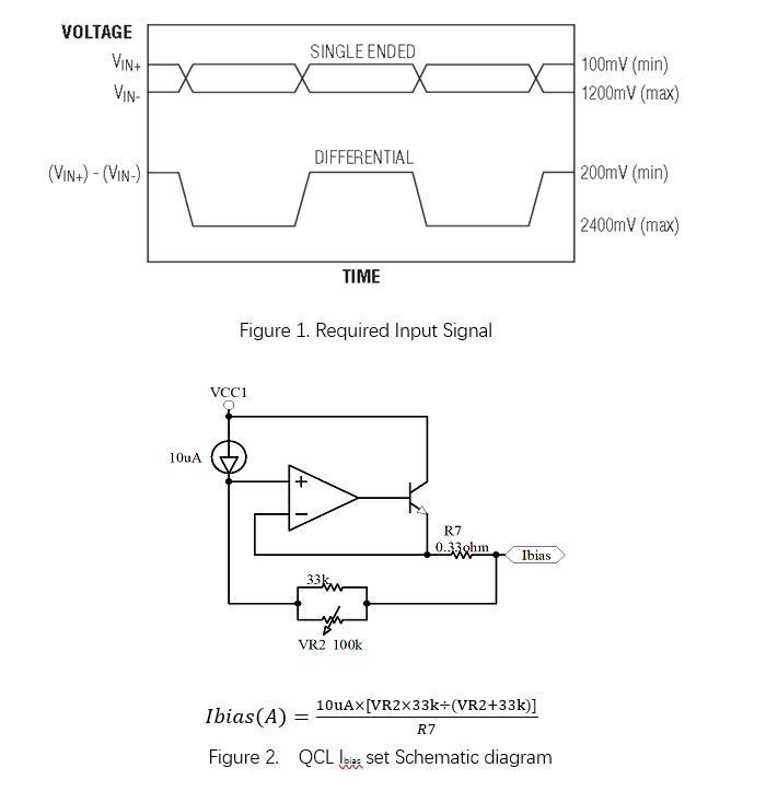
机械结构
